
One model, one dataset, and performance varying twofold depending on the defect type. On the reference dataset for steel surface defects, one study reports average precision per class of 0.501 for crazing, 0.649 for rolled-in scale, 0.791 for inclusions, 0.874 for pitted surfaces and 0.905 for scratches. Forty points between the hardest and easiest class.
That gap is not a shortcoming of the method, it is a property of the domain. Metal presents families of defects whose visual signatures have nothing in common: some are sharp and high-contrast, others blend into the normal texture of the surface. A project reasoning on average performance is systematically wrong about the classes that matter.
This article covers what is specific to defect detection on metal surfaces: the defect families and their individual difficulties, the particular case of welds, lighting suited to metal, and what public datasets cannot tell you. It extends the complete guide to defect detection.
Why metal is a special case in defect detection
Three physical properties make this family of materials considerably harder than it looks, and all three interact with lighting.Reflectivity
This is the property from which most of the following difficulties flow. A metal surface returns light specularly rather than diffusely. What is visible therefore depends as much on the geometry of the optical setup as on the actual state of the surface. Shifting the source or the part by a few degrees changes appearance radically, creating two distinct problems: variability in normal appearance that adds noise to learning, and reflections that locally saturate the sensor and mask information.Surface finish as a noisy background
This is where general-purpose detectors trained on natural images transfer worst. A metal part has no uniform appearance. Machining marks, rolling grain, brightness variation and lubricant residue produce a structured background against which a fine defect must be distinguished. It is the opposite of a homogeneous material where any irregularity stands out. On metal, the difficulty is separating normal irregularity from abnormal irregularity, and that boundary is sometimes undecidable without knowing the process.Variability between batches and grades
A final property complicates matters: the normal appearance of a metal surface depends on grade, batch, supplier and sometimes production season. The same reference can show visibly different surface finishes from one month to the next with no defect involved. A corpus assembled from a single batch therefore produces a model that learns the characteristics of that batch as much as the defects sought, and the first delivery of a different batch triggers a wave of unjustified alerts. Covering several batches in the initial corpus is a design requirement rather than a later improvement.The defect as a process signature
Metal defects are not random accidents, they are signatures of manufacturing conditions. The literature ties them explicitly to their origin: crazing corresponds to a network of visible cracks caused by tensile stress, while inclusions are formed by compounds such as oxides and sulfides created during melting, and are common in all metallic alloys. Knowing the cause is not merely of academic interest. That causality has an important practical consequence: defects arrive in waves correlated with a process incident rather than uniformly distributed. A corpus collected over a short period can therefore contain one defect type in bulk and none of the others, which distorts any prevalence estimate.The taxonomy of surface defects
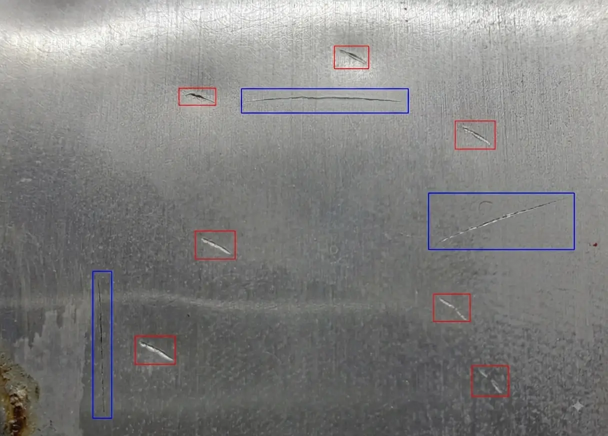
The reference dataset for steel defect detection sets a widely reused vocabulary: 1,800 greyscale images of hot-rolled steel sheets at 200 by 200 pixels, categorised into six defect types, crazing, inclusion, patches, pitted surfaces, rolled-in scale and scratches, localised by bounding box. That vocabulary is worth knowing, but it is not sufficient. These six families split into two groups from an annotation standpoint. Sharp-edged defects, namely scratches, patches and pits, are spotted and delineated without major ambiguity once the protocol is written. Diffuse defects, crazing and rolled-in scale, have blurred limits and a texture close to the background, which produces both weak inter-annotator agreement and mediocre model performance. The two phenomena are linked, and the second is partly caused by the first. A dataset closer to industrial reality broadens that list considerably: 3,570 images from real steel plates, across ten categories including punching, weld line, crescent gap, water spot, oil spot, silk spot, inclusion, rolled pit, crease and waist folding. The difference in scale and origin matters, and it contains categories absent from the academic set, notably liquid soiling, which raises a fundamental question: is an oil spot a product defect or contamination to ignore? The answer belongs to the quality reference and must be settled in the protocol.Not all defects are equal
The performance disparity noted in the introduction should concretely steer how a defect detection project is run. Three consequences follow. The first is budgetary: annotation and control effort should concentrate on the difficult classes. Double reading uniformly means spending on scratches that pose no problem while under-resourcing crazing, where disagreement is real. The second is methodological: metrics must be reported class by class, without exception. Satisfactory average performance can hide a class at fifty per cent, and if that class is the one triggering scrap, the system is unusable despite a good headline figure. The third bears on commercial scoping. A global quality commitment makes no sense on this kind of corpus. A differentiated commitment, more demanding on sharp classes and explicitly more cautious on diffuse ones, is both more honest and easier to hold.Welds, a distinct defect detection problem
Weld inspection belongs to defect detection but follows rules of its own, and treating it as surface inspection leads to errors. Three differences justify handling welds separately. The first is modality. Surface inspection sees almost nothing of what matters here, because critical weld defects are internal, which requires transmission imaging rather than reflection. The description of an industrial radiographic corpus gives the domain vocabulary: circular pores, elongated slag inclusions, linear lack-of-fusion indications, continuous dark penetration lines and sharp-contoured crack features, with appearances varying significantly in shape, size, contrast and continuity, some defects showing clear contours while others are weakly contrasted or partially obscured by background noise, to the point of being difficult to distinguish with the naked eye. The second difference is criticality. An isolated pore is often tolerated, a lack of fusion or a crack almost never is, because their planar nature makes them propagating. The decision rule is therefore strongly asymmetric between classes, and the annotation protocol must reflect that hierarchy: confusing a pore with a crack does not carry the same cost in both directions. The third difference is normative. Weld inspection is governed by reference standards defining acceptance levels, and the annotation ontology benefits from aligning with that vocabulary rather than inventing one. It eases acceptance by inspectors and avoids a mapping exercise later.Machining and dimensional defects
A third family stands apart in metal defect detection: deviations of shape and dimension, which are not appearance defects. The distinction matters because it points to a different technology. These belong to measurement rather than recognition, and are often better handled by three-dimensional vision or metrology than by a learning model trained on images. A machining inspection project must therefore explicitly separate what concerns appearance, burrs, tearing, tool marks, chatter, from what concerns dimension, so as not to assign the model a task an instrument does better. Some machining defects sit in between the two categories and deserve attention. Chatter marks, for instance, are both a visual pattern and a symptom of cutting conditions. Annotating them as an appearance defect is possible, but their value often lies in their diagnostic use for machine setup, which suggests retaining their periodicity or orientation as attributes rather than limiting the record to their presence.Foundry, sheet metal, surface treatment
The term metal surface covers situations whose defects have almost nothing in common, and separating them at scoping is worthwhile. Three broad contexts are worth naming, because a project scoped for one will not transfer to another. In foundry work and on raw parts, the surface is rough and irregular by nature. The defects sought are shrinkage cavities, surface blowholes, flash and sand inclusions, against a background whose texture is itself highly variable. The main difficulty is defining normality, since two conforming parts from the same mould differ visibly. In sheet metal and rolled products, the surface is regular and the background little textured, which makes fine defects detectable but demands high resolution across substantial widths, hence multi-camera arrangements whose stitching must be managed. After surface treatment, paint, anodising, coating, the defects change nature again: runs, craters, coverage gaps, shade variation. Difficulty shifts towards colorimetry, with all the lighting stability constraints that implies. A defect detection system designed for one of these three contexts does not transfer to the others without reworking both the setup and the corpus.Coils, sheets and the unit of inspection
On continuous products, coil, strip, wire, one question has to be settled before annotation begins and is easy to miss: what constitutes an inspection unit. The question sounds administrative and is not. There are no natural boundaries on a running coil. The image is a continuous reconstruction, and the choice of segment length is arbitrary but consequential. Too short and a long defect spans several units, which breaks counting and makes the conformity rule ambiguous. Too long and defect density per unit rises to the point where a single flaw fails an entire segment. Three conventions must accompany that choice in a defect detection protocol: how a defect straddling two segments is handled, how the position along the coil is recorded so a defect can be physically located afterwards, and whether the conformity decision applies per segment, per metre or per coil. None of the three can be reconstructed after the fact from images alone.Lighting suited to metal
As on every material, but more so here, the optical setup is the main lever for defect detection on this material, more so than on others. Getting this right does more for a project than any change of architecture. Four configurations cover most needs, and the choice follows from the physical nature of the defect rather than from preference. Dark-field lighting, where grazing light reaches the sensor only if deflected by an irregularity, turns a sound surface into a black background and brings out scratches and pits with considerable contrast. Diffuse dome lighting conversely suppresses reflections and suits colour or texture defects on glossy surfaces. Structured lighting projects a pattern whose deformation reveals shape defects. Backlighting, finally, suits only cut parts and reveals contours and missing matter. The choice is rarely made once and for all: many installations acquire several images of the same part under different lighting, which markedly improves detectability but requires the annotation protocol to state which view is authoritative for each defect type. Without that, two annotators looking at two different views will produce disagreements wrongly attributed to the ontology.What public datasets do not tell you
Academic defect detection datasets are useful for becoming familiar with defect families and for comparing architectures. They mislead as soon as a performance expectation is drawn from them. Two problems recur. A review of the field’s reference datasets notes explicit limits on the most used of them: it is one of the smallest datasets, both in image size and sample count, and it contains no dedicated test data, which makes comparing two algorithms’ metrics on it impossible since the test splits differ. The gap with real industrial data is measurable and large. A recent model reports classification accuracy of 91.72 per cent and mean average precision of 83.03 per cent on the academic set, against 76.73 per cent classification precision and 65.03 per cent mean average precision on the set drawn from real industrial plates. The same model, the same task, and nearly twenty points of difference depending on data origin. The practical conclusion matches the one set out in the field’s general guide: a published figure means something only relative to its conditions, and a project’s performance commitment must be built on a pilot batch from the real line, not on a transposition.Ontology and protocol in metal defect detection
Four points must be settled in writing in the annotation protocol, and they recur on almost every project. None of them is exotic; all four are settled routinely on mature projects and skipped routinely on immature ones. The distinction between defect and soiling comes first, and it carries more consequence than it appears. Oil traces, lubricant residue, dust, temporary markings: the protocol must say whether these constitute a separate class, grounds for rejecting the image, or something to ignore. Without a rule, each annotator will decide differently. The aggregation rule comes next, and it is the one most often left implicit. Is crazing one defect covering an area, or a multitude of micro-cracks? Does a row of aligned pits form one defect or several? The answer determines counting and therefore the conformity measurement, and it must be illustrated with examples rather than stated abstractly. Delineating diffuse defects is the third point. On a crazing zone with a gradual border, an explicit convention is needed: include the whole altered area, or only the part where cracks are individually visible. Both options are defensible, neither follows from common sense. Severity, finally, must rest on criteria that can actually be measured on the image. On metal, length, apparent depth, area density and position relative to functional zones are objectifiable criteria, unlike a general appreciation of severity.Quality control of metal defect annotation
The control arrangement follows the general logic set out in the guide, with two material-specific inflections. Both follow from points already made and are easy to apply. The first is mandatory stratification of control by defect type, given the documented difficulty gap. Uniform control over-represents easy classes and says nothing about the problematic ones. The second is stratification by lighting condition and by source, since a corpus combining images from several lines or setups must be controlled separately for each. One practice is particularly useful on this material: having a sample of contested cases arbitrated by a quality inspector who knows the process. Their ability to tie an appearance to a manufacturing cause settles cases no visual rule can separate, and their arbitrations enrich the reference case library decisively.Pre-annotation and what recent models contribute
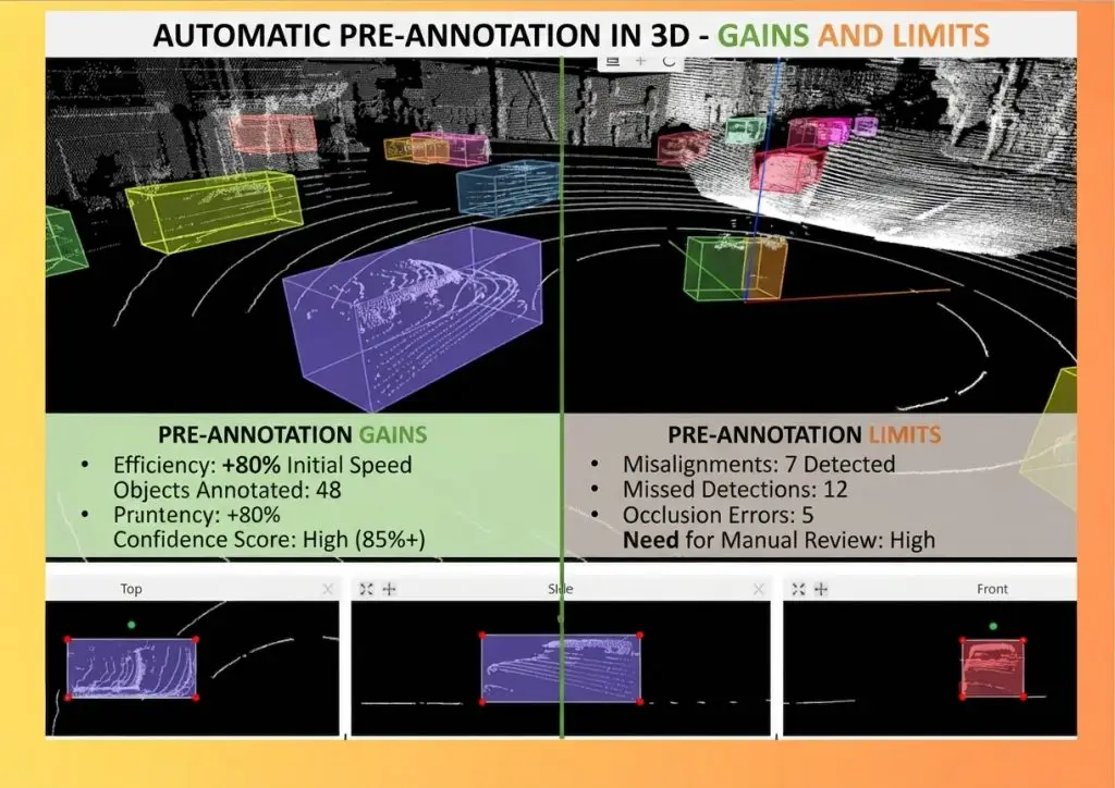
Steel is among the best covered materials in the literature, which makes pre-trained models unusually accessible. A sheet metal defect detection project can start with usable pre-annotation before its own data has even been collected. The picture is more nuanced than that availability suggests. The benefit is real and immediate on sharp classes. It shrinks sharply on diffuse ones, exactly where the need is greatest, which limits the expected economic gain: automation absorbs the easy work and leaves the expensive work. A budget built on an average gain will be overrun. Two cautions apply. The first is anchoring: on a crazing zone with a blurred border, an annotator will accept a proposal more readily than correct it, and the model’s error propagates into the ground truth. The second is line specificity: a model trained on plates of another grade, another mill or under different lighting produces plausible but systematically skewed proposals, which is more dangerous than no proposal at all.Estimating effort on metal
Two factors dominate the cost of a metal inspection corpus and neither is the image count. The first is the proportion of diffuse classes in the ontology, since a corpus dominated by crazing and scale costs several times one dominated by scratches and patches, for the same volume. The second is the number of distinct acquisition contexts, since each grade, each mill and each lighting arrangement effectively constitutes a sub-corpus with its own protocol checks and its own control stratum. Estimating credibly therefore means timing per class on a pilot drawn to span the real mix, and counting acquisition contexts as a multiplier rather than a detail. A quotation built on total image count alone will be wrong in a predictable direction.The most common mistakes in metal defect detection
These failures recur often enough across metal inspection projects that naming them is usually enough to avoid them.- Reasoning on average performance when the gap between classes reaches forty points.
- Failing to settle the status of soiling and oil traces in the protocol.
- Omitting the aggregation rule for multiple or diffuse defects.
- Treating weld inspection as surface inspection.
- Assigning the model dimensional deviations that metrology measures better.
- Acquiring under several lighting setups without stating which view is authoritative.
- Extrapolating academic benchmark performance to industrial plates.
- Collecting the corpus over a short period and underestimating defect correlation with process.
- Controlling uniformly instead of stratifying by class and acquisition condition.